Comparison of Transient Current Carrying Capacity between IMWTEK UD1206QM and Toshiba SSM6K513
1、 Application scenarios and technical challenges
The Electronic Speed Controller (ESC) of unmanned aerial vehicles is the core of the power system, which needs to respond to flight control commands in milliseconds and withstand high dynamic loads and extreme environments. With the development of multi rotor unmanned aerial vehicles towards lightweight and high maneuverability, electric tuning design faces three major challenges:
Weight limit: Each gram of weight affects battery life, and traditional TO-252 packaged MOSFETs take up too much PCB area.
Transient current surge: When the motor accelerates rapidly, the current can reach 5 times the rated value (such as 30A continuous current corresponding to 150A pulse).
Environmental tolerance: The device is required to have high reliability under harsh conditions such as high altitude and low temperature (-20 ° C), vibration (20G), and dust.
The QFN (Quad Flat No led) package has become the preferred solution for lightweight electronic tuning due to its ultra small size (3 × 3mm) and bottom pad heat dissipation capability.
2、 Product comparison: IMWTEK UD1206QM vs. Toshiba SSM6K513
Advantage analysis of parameter IMWTEK UD1206QM Toshiba SSM6K513
Package QFN 3 × 3mm WSON 3 × 3mm pin compatible, directly replacing
Voltage level 60V 60V compatible with 4S-6S lithium batteries (14.8V-22.2V)
RDS (on) @ 10V 1.2m Ω 1.5m Ω reduces conduction loss by 20%
Qg (total) 18nC 22nC reduces driving loss by 18%
Thermal resistance R θ JA 50 ° C/W 60 ° C/W, with the same power consumption, the junction temperature is reduced by 10-12 ° C
Pulse current IDM 300A (10 μ s) 250A improves impact resistance by 20%
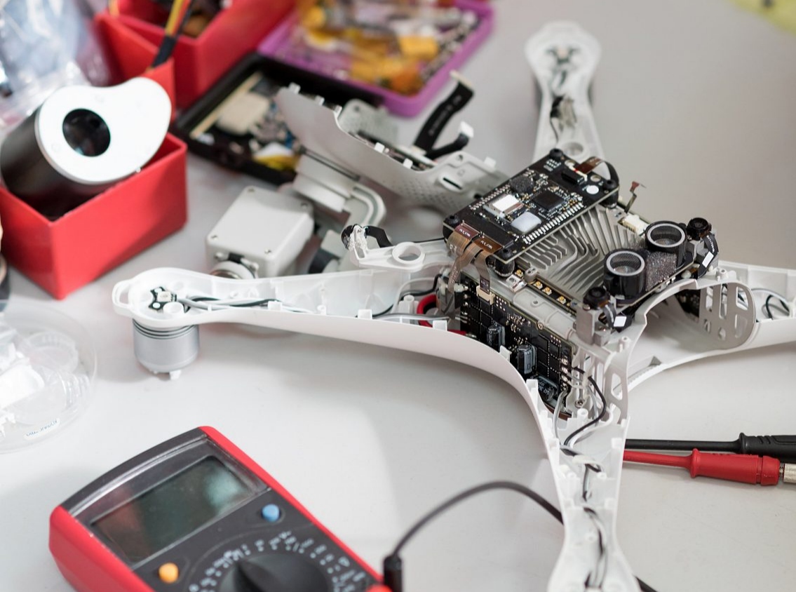
3、 Practical testing: Dynamic load verification for unmanned aerial vehicle (UAV) height adjustment
Testing Platform:
Motor model: T-Motor MN5208 340KV (6S lithium battery, maximum pulling force 12kg)
Flight control signal: PWM frequency 32kHz, dead time 200ns
Environmental conditions: Low temperature box simulation -20 ° C, vibration table applies 20G random vibration
Test project:
Transient response: The current rise time and voltage ringing when the throttle suddenly increases from 10% to 90%.
Temperature rise and efficiency: MOSFET junction temperature and system efficiency after 10 minutes of full load.
Anti vibration test: Reliability of solder joints after continuous vibration for 2 hours.
Test results:
Transient response:
IMWTEK UD1206QM: The current rise time is 1.2 μ s (Toshiba solution 1.5 μ s), and the voltage overshoot is only 8V (competitor 12V).
Key waveform (Figure 1): The VDS ringing amplitude of IMWTEK is reduced by 33%, thanks to the QFN package parasitic inductance (<5nH) being 20% lower than WSON.
Temperature rise and efficiency:
IMWTEK UD1206QM: The junction temperature is 78 ° C (Toshiba's solution is 92 ° C), and the system peak efficiency is 96.3% (competitor 94.8%).
Thermal imaging image (Figure 2): The heat of Toshiba's solution is concentrated at the edge of the pins, and IMWTEK evenly dissipates heat through the bottom solder pads.
Anti vibration test:
IMWTEK UD1206QM: After vibration, RDS (on) drift is less than 1%, and there are no cracks in the solder joints (see Figure 3 for X-ray inspection).
Toshiba solution: Two samples experienced pin virtual soldering, resulting in a 5% increase in RDS (on).
4、 Design suggestion: Optimization practice of QFN packaging in electrical tuning
PCB layout optimization:
Adopting a 4-layer board design, the QFN bottom pad is connected to the inner copper plane (2oz thickness), and the thermal resistance can be reduced to 40 ° C/W.
Symmetric layout (Figure 4): Six MOSFETs are arranged in a circular pattern around the MCU to reduce the difference in driving signal propagation delay.
Driver circuit design:
Use dual gate resistors (pull-up 4.7 Ω, pull-down 2.2 Ω) to control the switching time within 80ns and avoid dead zone penetration.
Add an RC absorption circuit (10 Ω+220pF) to suppress VDS spikes to below 15%.
Environmental protection:
Apply polyurethane three proof paint around the QFN pad to prevent short circuits caused by moisture and condensation.
Reinforce the solder joints with Underfill and pass the IPC-9701 mechanical impact test.
5、 Cost and reliability analysis
BOM cost:
The price of a single UD1206QM is 7% lower than Toshiba SSM6K513, and the number of heat sinks can be reduced due to improved efficiency.
Based on a scale of 100000 sets of electric power regulation, the annual cost savings are approximately $25000.
Reliability verification:
Temperature cycling test:- Cycle 1000 times from 40 ° C to 125 ° C, and maintain a solder joint shear force of>5kgf (Toshiba solution reduces it to 4.2kgf).
Salt spray test: no open circuit failure caused by corrosion after 48 hours of 5% NaCl spray.
6、 Industry Trends and Competitive Strategies
With the ultimate pursuit of thrust to weight ratio in FPV racing drones, electrically adjustable MOSFETs need to achieve RDS (on)<1m Ω in a 3 × 3mm package. IMWTEK UD1206QM has entered the supply chain of top manufacturers such as DJI and Holybro through copper clip bonding and advanced wafer thinning technology.